Loop Wiring Diagram Instrumentation Pdf
Instrumentation and control (i&c) personnel must demonstrate a familiarity level. Used for the automated production of instrumentation documents such as, instrument data sheets, loop diagrams, hook up diagrams, wiring /terminal strip diagrams, instrument index report, bill of materials report, cables schedule report, interconnection.
Loop Powered Instrument Wiring Diagram Wiring Diagram
All cabling and wiring has been installed, tested and labeled, recorded on the cable test report and witnessed/accepted by owner representative.

Loop wiring diagram instrumentation pdf. Piping and instrumentation (p&id) diagram shows the several instrumentation loops connected with particular equipment. Loop diagrams are imagined and understood by many people as a kind of extended wiring diagrams. Basics 19 instrument loop diagram :
7 symbols 7.1 instrument connection and action information. Loop diagrams are the most detailed form of diagrams for a control system and thus it must contain all details omitted by pfds and p&ids alike. Please choose a year from the menu at left to start your search.
I&c personnel must demonstrate a familiarity level knowledge of doe and industry codes and standards and their applicability as. The diagram is shown with 6a lighting fuse and 32a. Instrument loop diagrams are also called instrument loop drawings or loop sheets.
Instrument loop diagram that information is spread among many other documents and is not readily available. The source is at the outlet and a switch loop is added to a new switch. Instrumentation and loop diagram software.
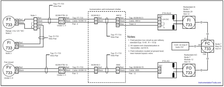
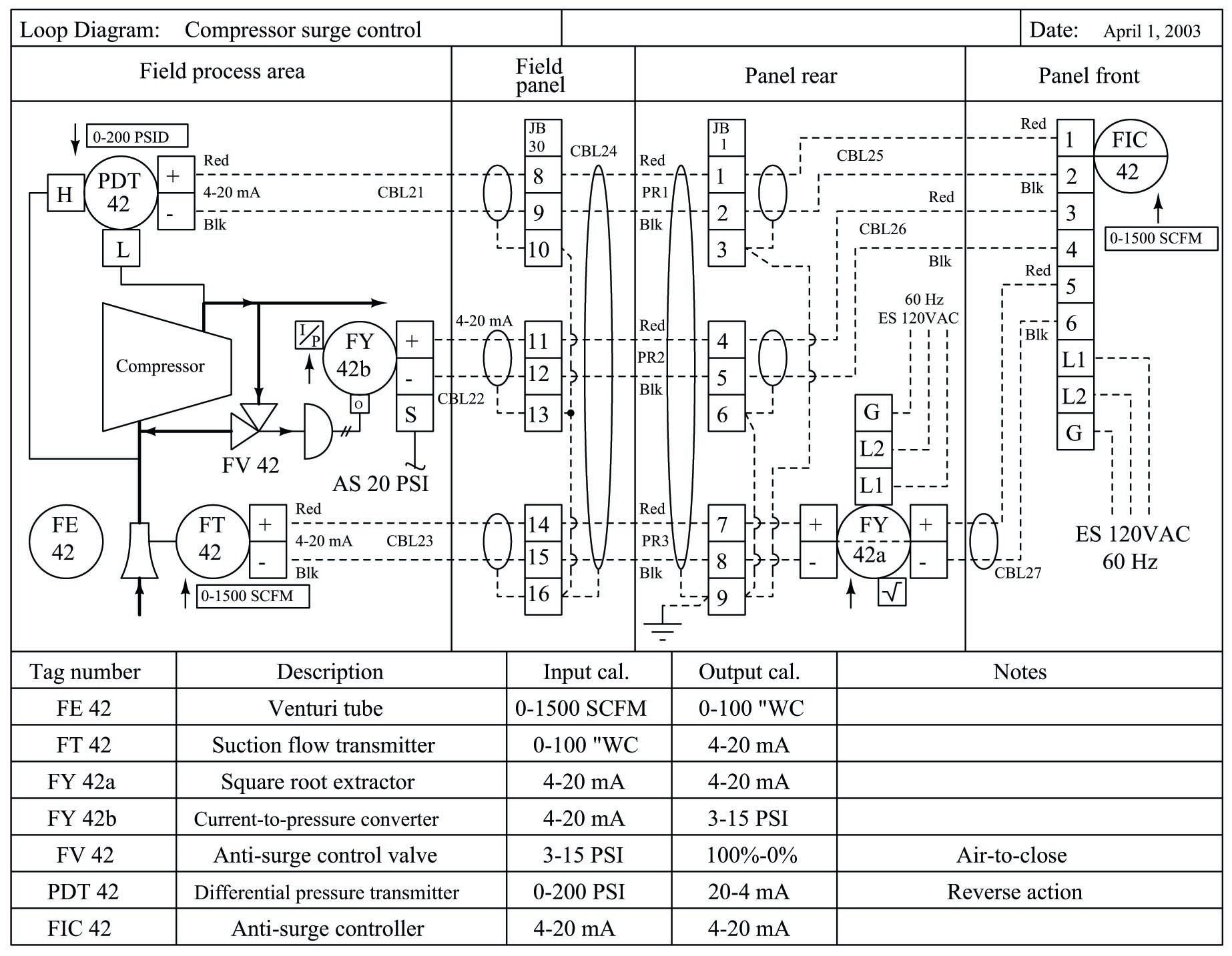
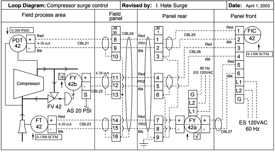
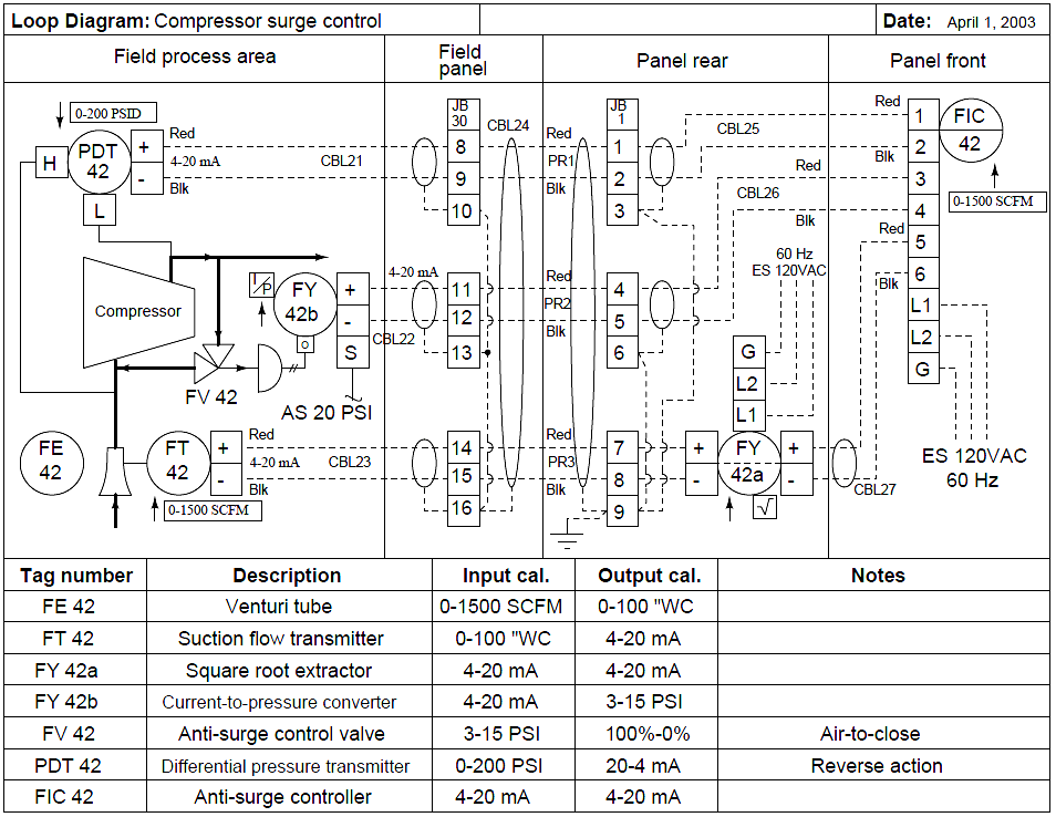
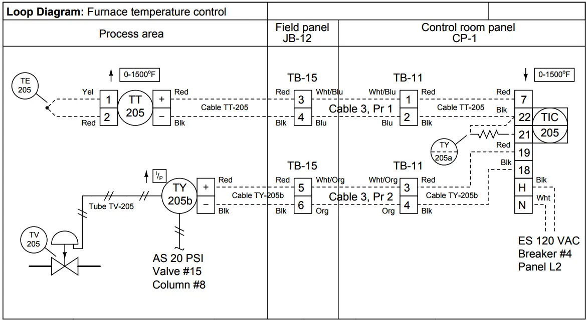
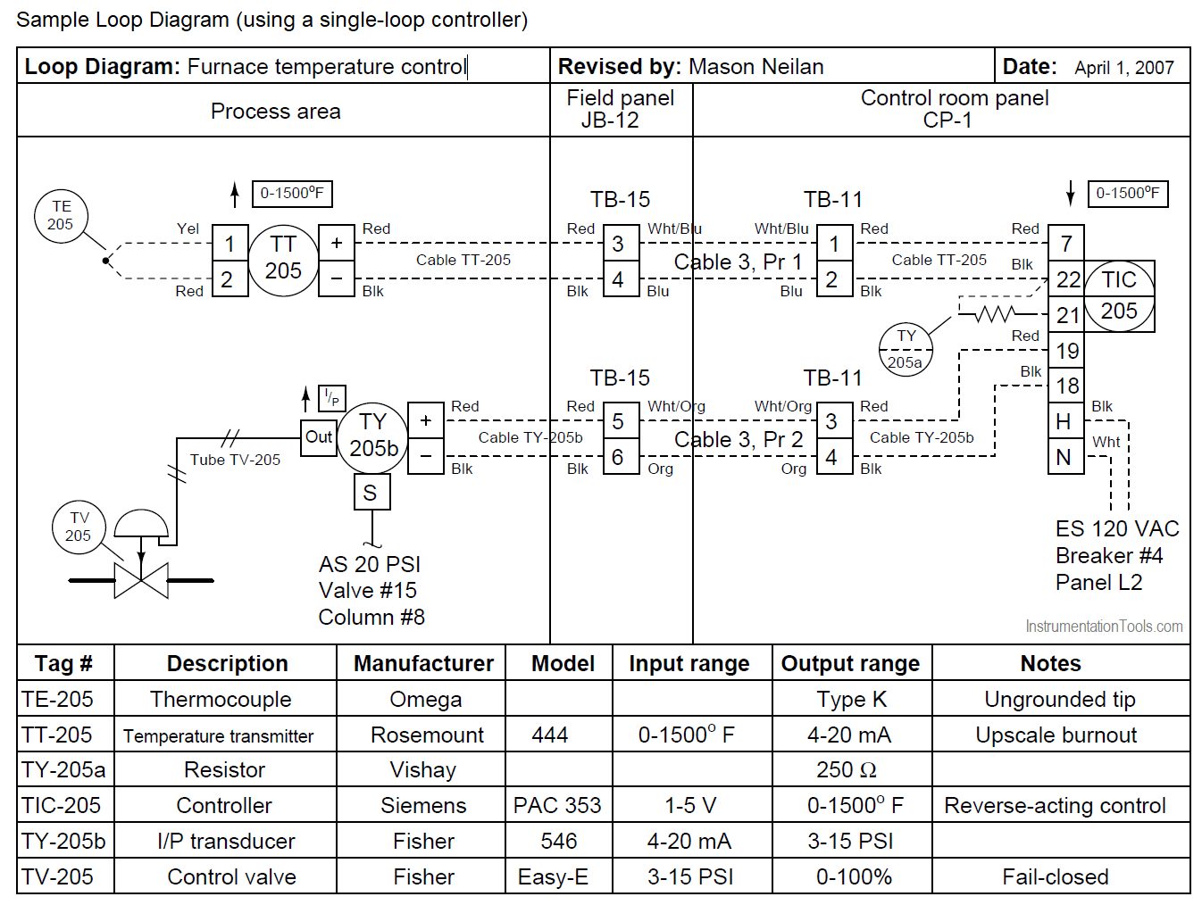
When a loop diagram shows you exactly what wire color to expect at exactly what point in an instrumentation system, and exactly what terminal that wire should connect to, it becomes much easier to proceed with any troubleshooting, calibration, or upgrade task. Is the least efficient diagram among the electrical wiring diagram. 1) identification of the loop and loop components shown on the p&ids.
Loop diagrams are fairly constrained in their layout as per the isa 5.1 standard. The hot and neutral terminals on each fixture are spliced with a pigtail to the circuit wires which then continue on to the next light. This understanding possibly comes from outputs by various design automation tools such as smartplant.
Instrument cable connects a right angled 1 4 jack to a 4 pin mini connector for bodypack transmitters. The process is illustrated in sections or subsystems of the process called loops. 2) word description of loop functions within the title.
Loop diagrams are fairly constrained in their layout as per the isa 5.1 standard. Wiring charm i/o in spi introduction the user experience on a project with over 50,000 i/o while several wiring methods were used on the project, this presentation will focus on the use of electronic marshalling reasons for using electronic marshalling on the project: Loop wiring diagram instrumentation pdf.loop wiring diagram.
Although wiring data can be imported, the intricate nature of instrumentation usually prevents a fully automated approach, and so wiring is still performed manually to make sure it matches the intended design. How to create an instrumentation loop drawing, say for instrument air vessel?. A common power supply can be used for both the transmitter and the control panel.
P&ids and loop diagrams p&ids and loop diagrams are construction and documentation drawings that depict the flow of the process and illustrate the instrumentation control and measurement interactions, wiring and connections to the process. The components within the loop have been installed in accordance with process piping, instrument air piping, mounting details and instrument drawings. This diagram illustrates wiring for one switch to control 2 or more lights.
Basics 16 wiring (or connection) diagram : Basics 18 embedded conduit drawing : However, expansion of those symbols to include connection points, energy source (electrical, air, hydraulic), and instrument action is necessary to provide the information required on instrument loop diagrams.
P&id shows the signal path of instruments and gives an overall picture of the connected loops in the system, whereas instrument loop diagram gives a clear idea of. Diagrams and help on uk electrical wiring. Loop diagram symbols and p&ids p&ids and loop diagrams p&ids and loop diagrams are construction and documentation drawings that depict the flow of the process and illustrate the instrumentation control and measurement interactions, wiring and connections to.
In case you ever expose the wires in your light fitting and assume only the brown wire is live. • to indicate the range of measured process variable and the engineering units • to indicate plc / dcs inputs and outputs for the loop • to indicate the location of the various control devices so that the external as well as the There can be only one transmitter output in any
The function of instrument loop wiring diagram is: Although wiring data can be imported, the intricate nature of instrumentation usually prevents a fully automated approach, and so wiring is still performed manually to make sure it matches the intended design. Loop wiring diagram instrumentation.a plot plan shows the exact location of each equipment.
As a minimum, an instrument loop diagram shall contain the information covered below. When a loop diagram shows you exactly what wire color to expect at exactly what point in an instrumentation system, and exactly what terminal that wire should connect to, it becomes much easier to proceed with any troubleshooting, calibration, or upgrade task. Basics 17 tray & conduit layout drawing :
These set of drawings are more detailed than process and instrument diagrams (p&ids).
Loop Wiring Diagram Instrumentation Pdf
Loop Diagrams (Loop Sheets) Control and Instrumentation Documentation Automation Textbook
Loop Wiring Diagram Pdf 37
Instrumentation Diagrams Multiple Choice Questions and Answers
ICD (Instrumentation control and design) Instrumentation Engineering
Loop Wiring Diagram Instrumentation Pdf 25
Instrumentation Trouble Shooting Instrumentation

Dcs Panel Wiring Diagram Pdf

Loop Wiring Diagram Instrumentation Pdf Diagram

Instrumentation Loop Diagrams Instrumentation Tools
Instrumentation Diagrams Multiple Choice Questions and Answers
Nikolay Bozov Industrial Automation and Control
Loop Wiring Diagram Instrumentation Pdf Diagram

Loop Wiring Diagram Instrumentation Pdf Diagram
Loop Powered Instrument Wiring Diagram Wiring Diagram

Instrumentation Loop Diagrams InstrumentationTools
Loop Wiring Diagram Instrumentation Pdf

loop diagram or instruments.pdf Cable Electrical Wiring Free 30day Trial Scribd
15 Loop Diagram Questions Instrumentation Tools