Alternator External Voltage Regulator Wiring Diagram
Each component should be set and connected with other parts in specific way. Injunction of 2 wires is usually indicated by black dot to the intersection of 2 lines.
Delco Alternator Wiring Diagram External Regulator Wiring Diagram

Alternator external voltage regulator wiring diagram.

Alternator external voltage regulator wiring diagram. This is the same place the red wire from the da plug connects. How to wire an external voltage regulator on a gm vehicle. Wiring diagram for alternator with external voltage regulator.
External regulator 3 wire ford alternator wiring diagram. To properly read a cabling diagram, one has to learn how the components in the method operate. Occasionally, the wires will cross.
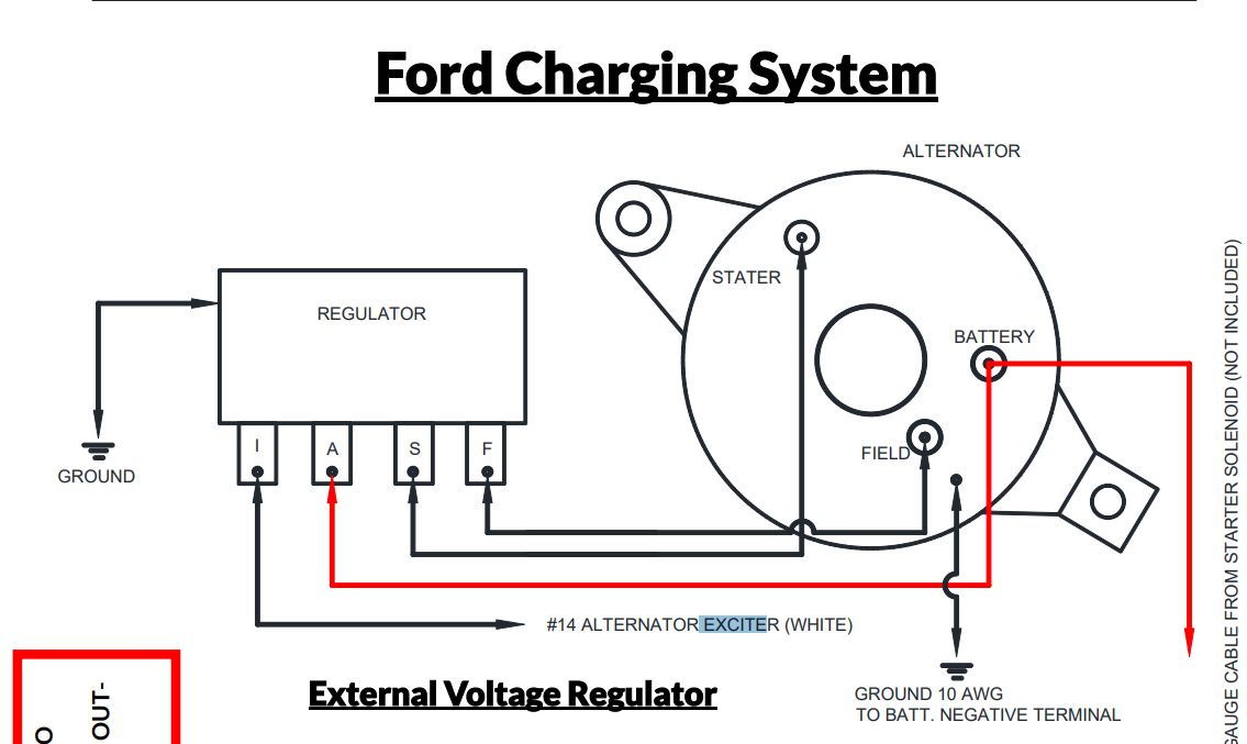
Refer to the simple diagram below for systems with an external electromechanical voltage regulator. Check the voltage at the bat terminal on the alternator. And connect the red wire to the output side of the alternator 10/32 stud.
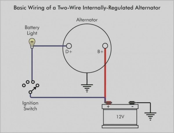
According to previous, the traces at a external voltage regulator wiring diagram represents wires. Battery positive cable, voltage sensing wire, and ignition wire. Alternator wiring diagram with external regulator wiring.
Check the voltage at the bat terminal on the alternator. The early gm alternator is the 10dn series alternator and was used on gm. Get the original quick start bypass kit from your service tech or we can help you diy it yourself demand the better quickstart kit for the emergency external.
There are two 10si models, the old external voltage regulator model and the newer internal voltage regulator model. A set of wiring diagrams may be required by the electrical inspection authority to agree to link of the address to the public electrical supply system. Alternator voltage regulator circuit schematic posted by margaret byrd posted on may 17 2018 automotive alternator schematic diagram of voltage regulator 4 solid state car joergs.
Wiring instructions for the early gm delco remy external regulated alternator. Wiring diagram arrives with several easy to stick to wiring diagram directions. External voltage regulator wiring diagram.
The circuit comprises three main wires: Leece neville 160 amp alternator wiring may 14 2019. Wiring instructions for the early gm delco remy external regulated alternator.
12 volt alternator voltage regulator diagram. Step #7 (figure 1) take the long red 10 gauge wire and connect to the back of the alternator 10/32 stud. Leece neville 8mr alternator prestolite new show posts mainesail self build adjule controler output wiring irv2 forums technical help with 5 wire and motorola voltage content electrical s3 figure 21 1 the digital multimeter 12v externally regulated 24 volt 40 amp 100 71 8329n advance 2020 charging green tractor talk internally diy low cost.
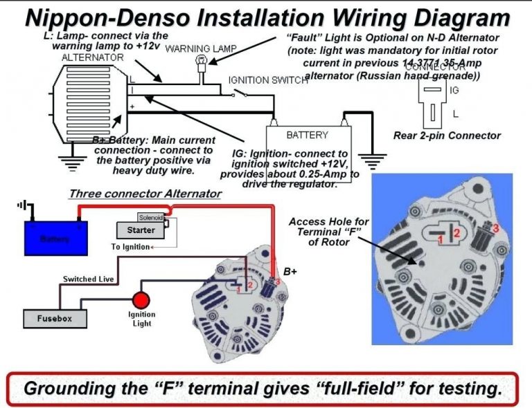
Can be used on the chrysler square back, nippondenso external regulated, bosch external regulated, mitsubishi external regulated units. I= charging indicator on instrument cluster. Diagram 1983 ford f 250 voltage regulator wiring diagram full 2000 ford f250 alternator wiring diagram wiring diagram.
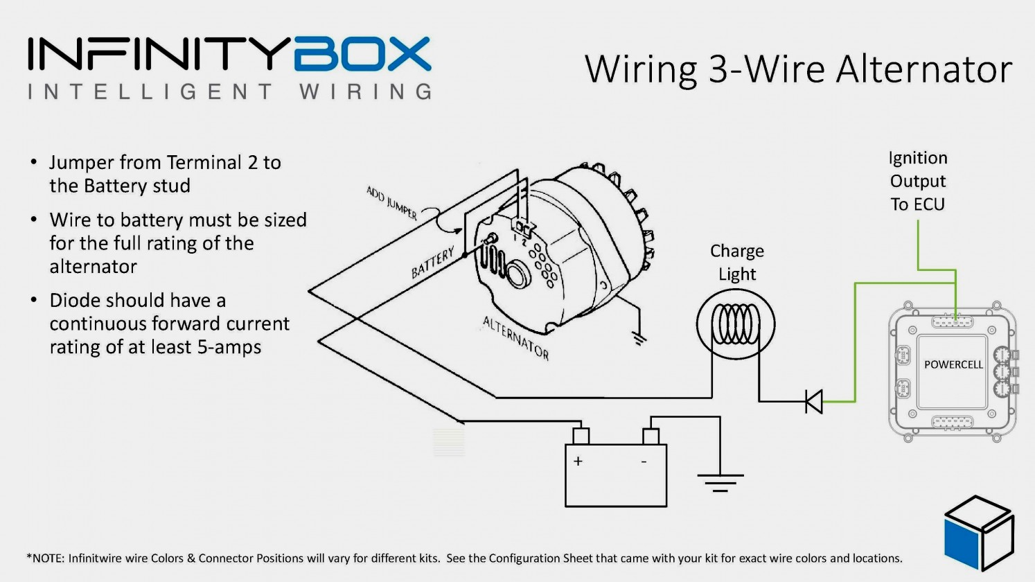
Connecting the sense wire to the batteries causes the alternator to output extra voltage to compensate for the voltage drop in the. Take the other end of the long red wire and connect directly to one terminal of. Nov 03, · neil, well, yes it does.
Step 2 locate the voltage regulator usually on the firewall. Wiring diagram arrives with several easy to stick to wiring diagram directions. Alternator voltage regulator wiring diagram wiring diagram is a simplified tolerable pictorial representation of an electrical circuit.
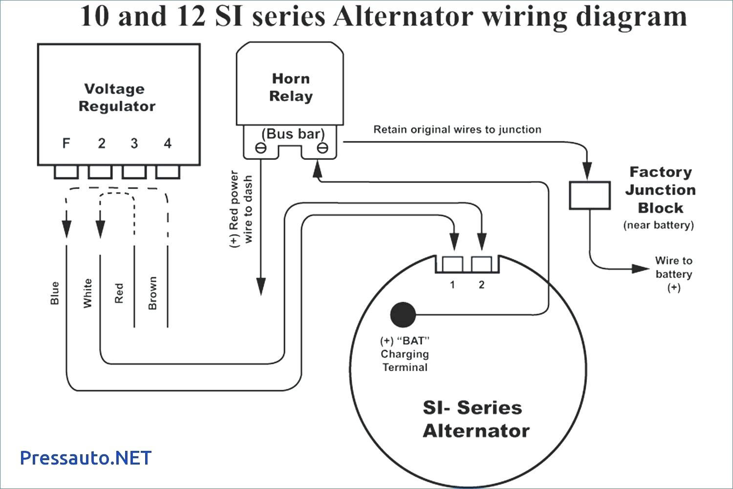
Voltage regulator wiring diagram you will want a comprehensive expert and easy to understand wiring diagram. Here is the 4 pin diagram, it has never changed over the years for external regulators. Position the alternate regulator on the side of the driver shock tower, which is next to the relays.
Connect the blue and green wirings. Wiring diagram for alternator with external regulator wiring diagram is a simplified gratifying pictorial representation of an electrical circuit it shows the components of the circuit as simplified shapes and the gift and signal associates in the midst of the devices. A wiring diagram is a simplified traditional pictorial depiction of an electrical circuit.
Mark the area and drill holes for mounting of bolts. These guidelines will likely be easy to grasp and apply. A wiring diagram is a streamlined conventional photographic depiction of an electric circuit.
It’s supposed to assist all the typical user in developing a suitable method. How to wire an external voltage regulator on a gm vehicle. For example , in case a module is powered up and it sends out a new signal of half the voltage in addition to the technician would not know this, he'd think he has a problem, as he would expect.
It represents the physical parts of the electrical circuit as geometric forms, with the real power and connection connections in between them as thin sides. If the voltage is less than 135v remove the plug connector at the voltage regulator. How to wire an external voltage regulator on a gm vehicle.
There’ll be primary lines that are represented by l1, l2, l3, and so on. A= battery, to alt and battery. As the name indicates it regulates the amount of voltage produced from the alternator to ensure a consistent voltage to the battery and electrical equipment in.
3 wire alternator wiring diagram source: Also, this product can be used as a wiring harness and external voltage regulator replacement kit for any 1987 and earlier chrysler family vehicle alternator with dual insulated brushes. The ignition input wire is attached to the engine.
F= field (alt) s= stator (alt) share. But, it doesn’t mean connection between the wires. A typical alternator wiring diagram with an external electromechanical voltage regulator.
A voltage regulator takes current from a battery with oscillating voltage and puts out constant voltage.
Alternator Wiring Diagram With External Regulator Wiring Library External Voltage Regulator
Wiring Diagram For Alternator With External Voltage Regulator Electrical Diagram Images Guide 2020

Gm External Voltage Regulator Wiring Manual EBooks External Voltage Regulator Wiring
External Regulator Alternator Wiring Diagram MORPHINEANDDRUGS
Repair Guides Engine Electrical Alternator

External voltage regulator woes plz help? Pelican Parts Forums

Delco Alternator Wiring Diagram External Regulator Wiring Diagram
External 12 Volt Voltage Regulator HVAC How To

6 pin voltage regulator wiring help Page 2 IH8MUD Forum
3Wire Alternator Regulator Diagram Seaboard Marine

External Voltage Regulator Wiring Diagram
Alternator Wiring Diagram With External Regulator Wiring Library External Voltage Regulator
Grounding alternator For B Bodies Only Classic Mopar Forum
Wiring Diagram For Alternator With External Regulator

Alternator Voltage Regulator Wiring Diagram Collection Wiring Diagram Sample
General Electric Voltage Regulator Wiring Diagram schematic and wiring diagram in 2020 Car

voltage regulator alternator wiring Diesel Forum

Alternator External Regulator Wiring Diagram Wiring Diagram Networks
Ford Alternator External Voltage Regulator Wiring Diagram Database
